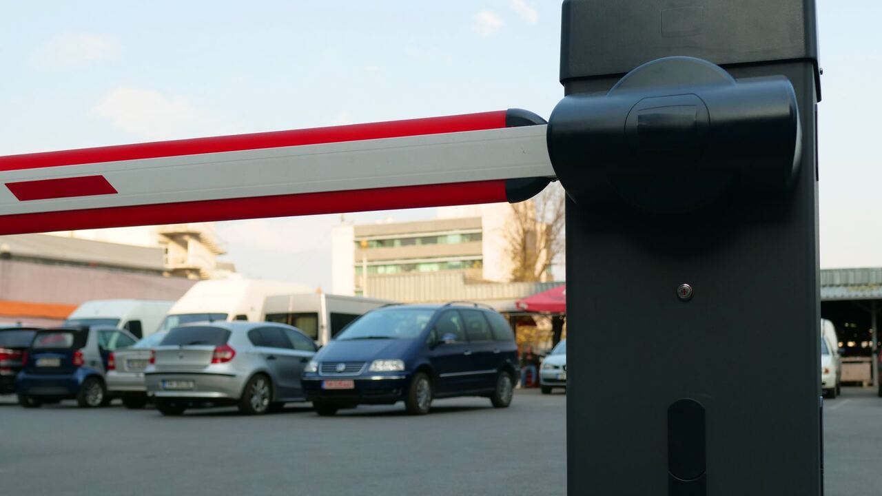
In the automation class, the parking barrier often becomes the first story problem. The button is pressed, the barrier rises, the buzzer sounds, the car passes, the buzzer stops, the barrier lowers. The sequence is easy to write. What causes confusion is one question: when can the barrier lower? The answer lies in the sensor, not in the timer.
Who does what in a lane
| Component | Location | Function |
|---|---|---|
| Open command (button, ticket, card) | post in front of the barrier | grants permission for the barrier to rise |
| Opening loop | just before the safety loop, at most 1 m away | automatically opens the barrier when a vehicle approaches, usually in the exit lane |
| Safety loop, also closing loop | under the arm of the barrier, extending at least 500 mm forward and backward from the arm | keeps the barrier open as long as there is a vehicle |
| Photo cell (light barrier) | post on the side of the lane | detects what the loop misses: people, bicycles, small motorcycles |
The loop is a cable embedded in the asphalt. The detector sends an alternating current of 10 to 200 kHz through the cable. When a metal body of a vehicle is above it, the inductance of the cable decreases, and the detector relay activates.
Five logic rules that must be met
- The barrier rises only if there is a valid command: button, ticket, card, or opening loop.
- While the safety loop or photo cell is active, the command to lower is ignored.
- The barrier only lowers after the vehicle leaves the safety loop. The Magnetic barrier manual states clearly: as long as the vehicle is standing on the loop, the barrier remains open. Lowering the barrier with just a timer does not meet this requirement.
- If the loop detects something while the barrier is lowering, its movement reverses. Therefore, the loop should not be too close to moving metal objects. The DoorKing manual notes that the gate's own movement can be read as a vehicle and trigger a reversal mid-cycle.
- One opening for one vehicle. In automatic closing mode, a second car that is too close behind risks being hit by the arm, so manufacturers require this to be prevented through layout or signage.
Motorcycles: the weak point of the loop
The NEMA standard cited by the FHWA tests detectors with a loop of 1.8 x 1.8 m with three turns. Cars change their inductance by about 3.2 percent. Small motorcycles only 0.13 percent, roughly 25 times weaker.
The consequences are real. DoorKing warns: if the loop fails to read a motorcycle, the arm can lower unexpectedly onto the rider. The Magnetic manual requests additional safety for vehicles with too small a metal floor. The same manual mentions that a closing arm can injure people, cyclists, and drivers of convertibles.
In lanes also used by motorcycles, a loop alone is not enough. Add a photo cell, or separate the lanes.
Loop installation figures
The figures below are summarized from the manuals of two barrier manufacturers and one detector manufacturer. The exact limits still follow the manual of the barrier you install.
| Parameter | Value |
|---|---|
| Groove depth | 50 mm, groove angle cut at 45° |
| Number of turns | 3 to 6, equivalent inductance of 70 to 500 µH |
| Short side of the loop | at least 46 cm; detection height about 1/2 to 2/3 of the short side |
| Safety loop for trucks | at least 2.5 m in the direction of travel |
| Distance to the edge of the road | 300 to 500 mm |
| Distance to rebar | at least 50 mm |
| Connecting cable to the detector | maximum 15 m, twisted about 6 times per foot (approximately 20 times per meter) |
| Distance between loops | at least 1.2 m, or the detector frequency must be differentiated |
| Cable connections | soldered, without twist connectors |
After the cable is placed in the groove, measure first before the groove is closed. One manual provides limits: inductance of 70 to 500 µH, contact resistance of 0.8 to 2.0 ohms, insulation to ground above 1 MΩ. Outside of that range, the loop is considered damaged.
If you prefer to see the story problem broken down directly, there is a short clip about the logic of parking barrier sensors. For the control side, also read the role of PLC and HMI in industrial automation.
Sources
- DoorKing, Inc., Underground Loops and Loop Detectors: Information Manual (Loop Info-S-5-22), 2022
- Magnetic Autocontrol, Operating Instructions Barrier MHTM MicroDrive Access and Parking (5815,5013US, Version 05), chapters 2, 7, and 8.4
- Diablo Controls, Inc., Technical Data: Vehicle Detection Using Inductive Loops, 2014
- Federal Highway Administration, Traffic Detector Handbook: Third Edition, Volume I, Chapter 2 (FHWA-HRT-06-108), 2006