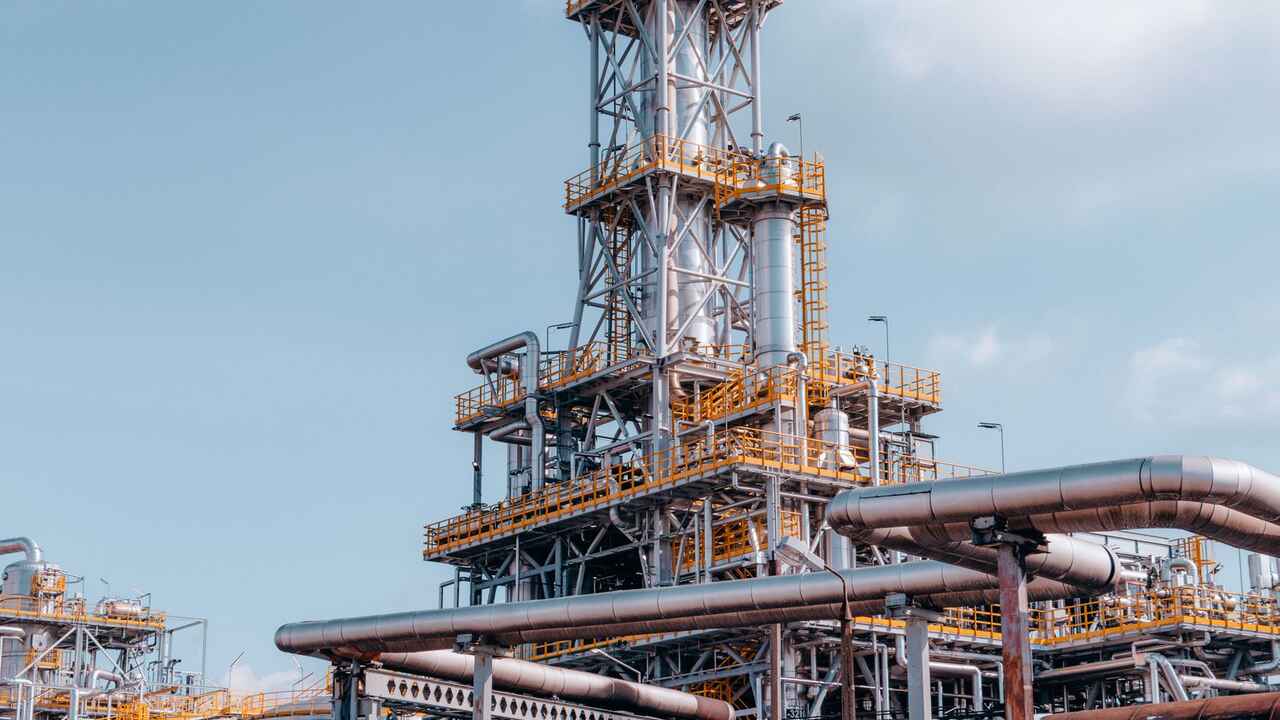
The tray distillation column has two limits that must not be exceeded: too little vapor and too much vapor. Between these two limits lies an operating window where separation occurs efficiently. The terms weeping, entrainment, and flooding are often mentioned in sequence as if they are part of a continuum, whereas each marks a different edge of that window. This article maps out who marks which edge, and what happens to separation when those edges are crossed.
Lower limit: weeping
Weeping occurs when liquid leaks down through the holes or valves of the tray, whereas it should flow across the tray and into the downcomer. The causes referenced in the technical literature include: insufficient vapor flow, resulting in the vapor rate through the holes being inadequate to hold the liquid above the deck. Therefore, weeping becomes the lower limit of vapor velocity.
The impact on separation: the leaking liquid bypasses the contact zone. A source from the Gas Conditioning Conference at the University of Oklahoma states that inlet weeping is the most detrimental, as the liquid bypasses contact at two tray levels simultaneously. The Petroleum Technology Quarterly review adds a design benchmark: a good tray should be able to operate at a minimum turndown of 4:1, and below the range of 3 to 4:1, liquid begins to leak through the tray.
Upper limit: entrainment, then flooding
Entrainment is the liquid that is lifted by vapor to the tray above it. This liquid is then recycled after reaching equilibrium on the upper tray, thus reducing efficiency. In the froth regime, the cause is high vapor rates; in the spray regime, the cause is a reduced liquid rate while the vapor rate remains high.
Flooding is the endpoint of this process. According to sources from the University of Oklahoma, jet flooding originates from large-scale entrainment; if it continues to rise, the column fills with liquid and cannot be operated. Flooding thus becomes the upper limit of vapor velocity. There is also flooding from the downcomer side: backup occurs when the pressure drop across the tray is too large or the downcomer gap is too narrow.
| Symptoms | Direction of deviation | What happens |
|---|---|---|
| Weeping | Vapor too low | Liquid leaks through holes, contact missed |
| Entrainment | High vapor | Liquid is lifted to the tray above, efficiency decreases |
| Flooding | Even higher vapor | Column fills with liquid, cannot operate |
Numbers to pay attention to
There is no single universal threshold. The Petroleum Technology Quarterly review notes that different vendors define the entrainment limit differently: some use 85 percent jet flood as the point where 10 percent of the liquid is carried over, while others use 80 or 90 percent with 10 or 20 percent carried over. Approaching that limit, the rate of entrainment is very sensitive to small changes in vapor rate, and the column becomes more difficult to control. Conventional design practice is to operate at 70 to 80 percent of the jet and downcomer flooding rates.
For calculations, the vapor velocity at the flooding point is commonly estimated using the Fair method as well as Kister and Haas, while the weeping velocity uses the Eduljee correlation, as outlined in Chemical Engineering magazine.
One term to be cautious about: dumping
Dumping is often mentioned alongside the three terms above. A 2016 AIChE paper by Daniel Summers includes it as a separate hydraulic parameter alongside flood, spray, backup, entrainment, and weeping, all of which can be illustrated on a single operating window diagram. However, other sources reviewed for this article do not define it uniformly. If you encounter this term in vendor documents, check the vendor's own definition before using it as a design threshold.
Why this window is monitored
The width of the window determines how flexible the column is to changes in load. As a vendor claim, not a general benchmark: in a case study by Koch-Glitsch published by the University of Oklahoma, the minimum load for FLEXIPRO valve trays is around 15 percent, compared to 60 percent for sieve trays. For operators, this means the same: keep the vapor and liquid rates between the two edges, and watch for signs approaching either edge, both efficiency drops and increased pressure drop.
For the context of fractionation columns in process simulations, see also oil and gas process simulation from CDU to NGL fractionation in HYSYS.
If you prefer to see the initial explanation directly, there is a clip at taalenta.id/video/ogs-apa-itu-entrainment-weeping-dumping-dan-flooding-di-kolom.
Sources
- Petroleum Technology Quarterly / Digital Refining, "Tray hydraulic operating regimes and selectivity": https://www.digitalrefining.com/article/1000503/tray-hydraulic-operating-regimes-and-selectivity
- Laurance Reid Gas Conditioning Conference, University of Oklahoma, "Distillation Tray Valve Features": https://ou.edu/content/dam/pacs/laurance-reid/documents/8.%20DISTILLATION%20TRAY%20VALVE%20FEATURES.pdf
- Chemical Engineering, "Entrainment, flooding and weeping velocities": https://chemengonline.com/entrainment-flooding-and-weeping-velocities
- D. Summers, "Distillation Tray Design Through Better Understanding of Operating Windows", AIChE Annual Meeting 2016: https://proceedings.aiche.org/conferences/aiche-annual-meeting/2016/proceeding/paper/102a-distillation-tray-design-through-better-understanding-operating-windows
- Chemical Processing, "A Visual Assessment of Distillation Tray Valve Performance" (May 2026): https://www.chemicalprocessing.com/show-coverage/echemexpo/article/55377766/a-visual-assessment-of-distillation-tray-valve-performance